|
|
5 years ago | |
|---|---|---|
| .. | ||
| Pictures | 6 years ago | |
| gerber | 6 years ago | |
| Readme.md | 6 years ago | |
Readme.md
Disclaimer
This PCB was kindly provided by a user (@mariolukas) of ESPuino and I (@biologist79) didn't test it myself. PCB-circuit is provided 'as is' without warranty. It was made to keep wiring much simpler. However, Mario stated it's working fine with his ESPuinos.
ESP32 I2S breakout carrier PCB
This is a simple PCB which makes wiring the whole stuff much easier. It contains connections for all components which are described in the projects wiring table. An ESP32 from AZ-Delivery was used but every pin-Compatible ESP32-board will do the job.
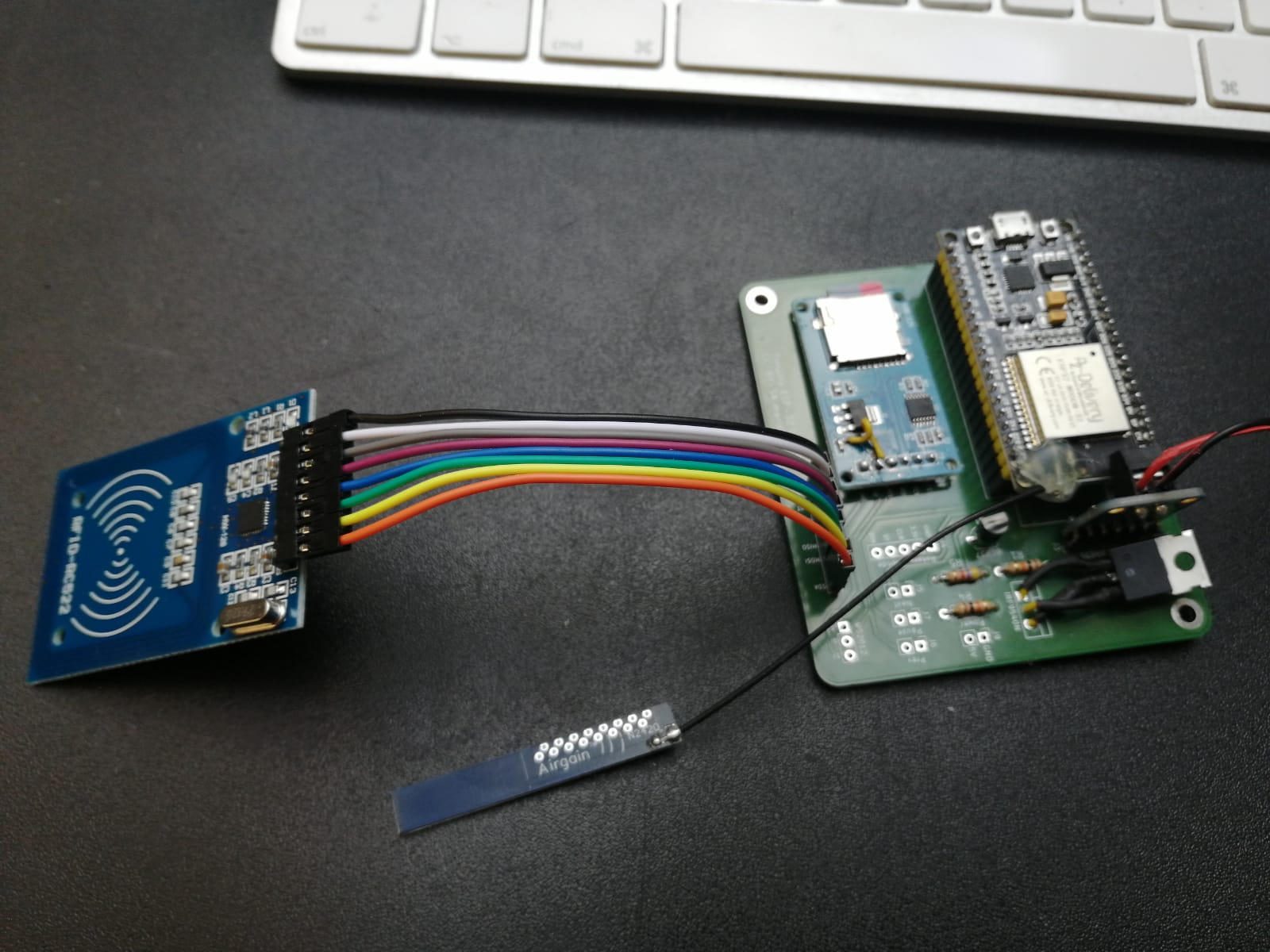 The image shows my first board which came with a litte wiring-bug. Don't worry: the bug is fixed in the current version. I ordered my board at aisler.net, there is already and upload-link available: https://aisler.net/p/YTYZJZMM. Gerberfiles (
gerber.zip) are also available, so ordering for instance at JCLPCB is also possible.
Features
- Fits ESP32 from AZ-Delivery
- Outer diameter: 72 x 82mm
- 2.54mm-connectors for all peripherals.
- NPN-transistor/pMosfet-circuit that switches off MAX98357a, Neopixel and uSD-card-reader automatically when ESP32's deepsleep is active (RC522 is directly driven by GPIO17).
- All peripherals are driven at 5V! Keep this especially in mind when choosing uSD-reader. Never use one without voltage-regulator! This one would fit for instance.
Prerequisites
- Edit
settings.hfirst according your needs. However, some settings are fixed: - Set HAL=1
- Disable
HEADPHONE_ADJUST_ENABLE,MEASURE_BATTERY_VOLTAGE,SD_MMC_1BIT_MODEandSINGLE_SPI_ENABLEas these are not supported - Edit
settings-lolin32.haccording the wiring-table below. Don't worry that your board isn't in fact a Lolin32. It's just there to make life easier for those, that use Lolin32, but that doesn't mean it wouldn't work with different boards.
PCB-wiring (2 SPI-instances: RC522 + SD)
Uses two SPI-instances. The first one for the RFID-reader and the second for SD-card-reader. Make sure to edit settings-lolin32.h according this table! Please refer Schematics.pdf for reference.
| ESP32 (GPIO) | Hardware | Pin | Comment |
|---|---|---|---|
| 5 V | SD-reader | VCC | |
| GND | SD-reader | GND | |
| 15 | SD-reader | CS | |
| 13 | SD-reader | MOSI | |
| 16 | SD-reader | MISO | |
| 14 | SD-reader | SCK | |
| 17 | RFID-reader | 3.3V | Directly connected to GPIO 17 for power-saving when uC is off |
| GND | RFID-reader | GND | |
| 21 | RFID-reader | CS/SDA | |
| 22 | RFID-reader | RST | |
| 23 | RFID-reader | MOSI | |
| 19 | RFID-reader | MISO | |
| 18 | RFID-reader | SCK | |
| 5 V | MAX98357 | VIN | |
| GND | MAX98357 | GND | |
| 25 | MAX98357 | DIN | |
| 27 | MAX98357 | BCLK | |
| 26 | MAX98357 | LRC | |
| --- | MAX98357 | SD | not connected |
| 34 | Rotary encoder | CLK | Change CLR with DT if you want to change the direction of RE |
| 35 | Rotary encoder | DT | Change CLR with DT if you want to change the direction of RE |
| 32 | Rotary encoder | BUTTON | |
| 3.3 V | Rotary encoder | + | |
| GND | Rotary encoder | GND | |
| 4 | Button (next) | ||
| GND | Button (next) | ||
| 33 | Button (previous) | ||
| GND | Button (previous) | ||
| 5 | Button (pause/play) | ||
| GND | Button (pause/play) | ||
| 5 V | Neopixel | V | |
| GND | Neopixel | G | |
| 12 | Neopixel | DI | |
| 17 | BC337-40 | Base |
Antenna-improvements
It is recommended to solder an external antenna to the ESP32 for preventing connection issues. Cheap ESP32 boards come with an antenna which is laying on the PCB. The newer ones provide an ESP32-board where the antenna-part protrudes over the edge.
You can find some useful tips for soldering an antenna to the old ones here: https://community.home-assistant.io/t/how-to-add-an-external-antenna-to-an-esp-board/131601